In Module 1, we analyzed the philosophical divide between the microkernel and the monolith. Today, we move into the hardware-software interface. For a CTO or systems architect, understanding the Virtual File System (VFS) and Memory Management Unit (MMU) is the difference between a system that scales linearly and one that chokes under enterprise I/O loads.
I. The VFS Layer: The Universal Translator of the Kernel
The Virtual File System (VFS) is perhaps the most elegant abstraction in the Unix kernel. It allows the operating system to provide a unified namespace for disparate storage types. Instead of implementing logic for every filesystem, the VFS provides a common set of objects and function pointers that treat every file-like object—whether it is a block device, a socket, or a pipe—as a consistent entity.
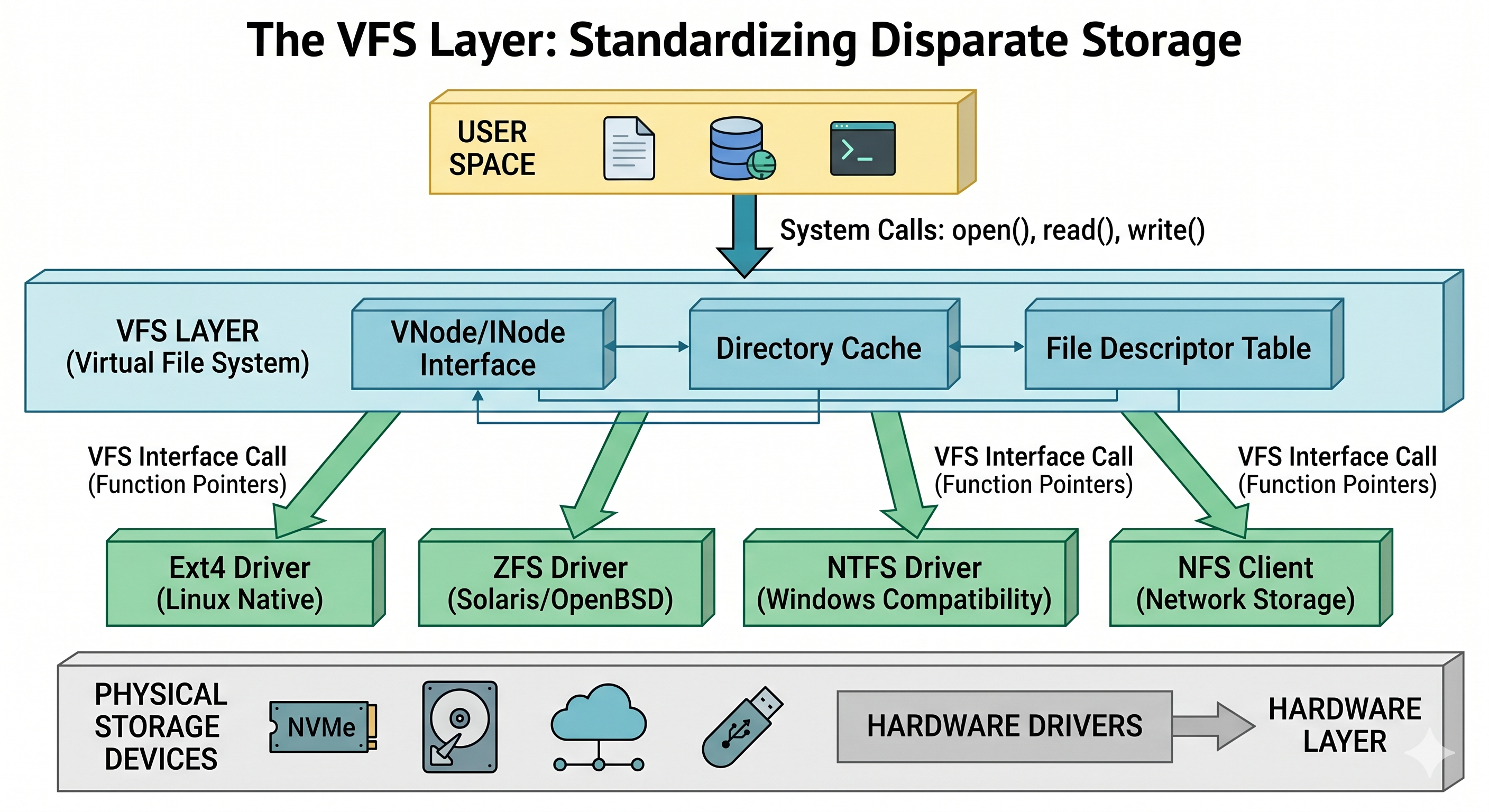
Figure 1: The VFS layer standardizes disparate storage across Linux, Unix, and Windows.
1.1 Data Structures: Vnodes, Inodes, and Dentries
To understand how EDpCloud achieves high-performance replication, one must look at the primary structures the VFS manages:
- The Inode Object: Represents a specific file on a physical disk, containing metadata and pointers to data blocks.
- The Vnode Object: A Virtual Node. While an Inode is tied to the disk, a Vnode is the kernel’s abstract representation. It contains the
v_opvector that routes system calls to the correct filesystem driver. - The Dentry (Directory Entry): A cache linking a filename string to an Inode. In a replication scenario involving millions of small files, Dcache efficiency determines the system’s “walk speed.”
II. Hardware Enforcement: The MMU and Memory Protection
If the VFS is the OS’s logic, the Memory Management Unit (MMU) is the physical law. It translates Virtual Addresses (the addresses seen by software) into Physical Addresses (the actual bits in RAM).
A hardware-level visualization showing the “fences” provided by the Memory Management Unit. On the left, it displays the Ring Protection model (Kernel vs. User Mode). On the right, it maps the flow of a memory request through the Translation Lookaside Buffer (TLB) and Page Tables, illustrating where “TLB Flushes” occur.
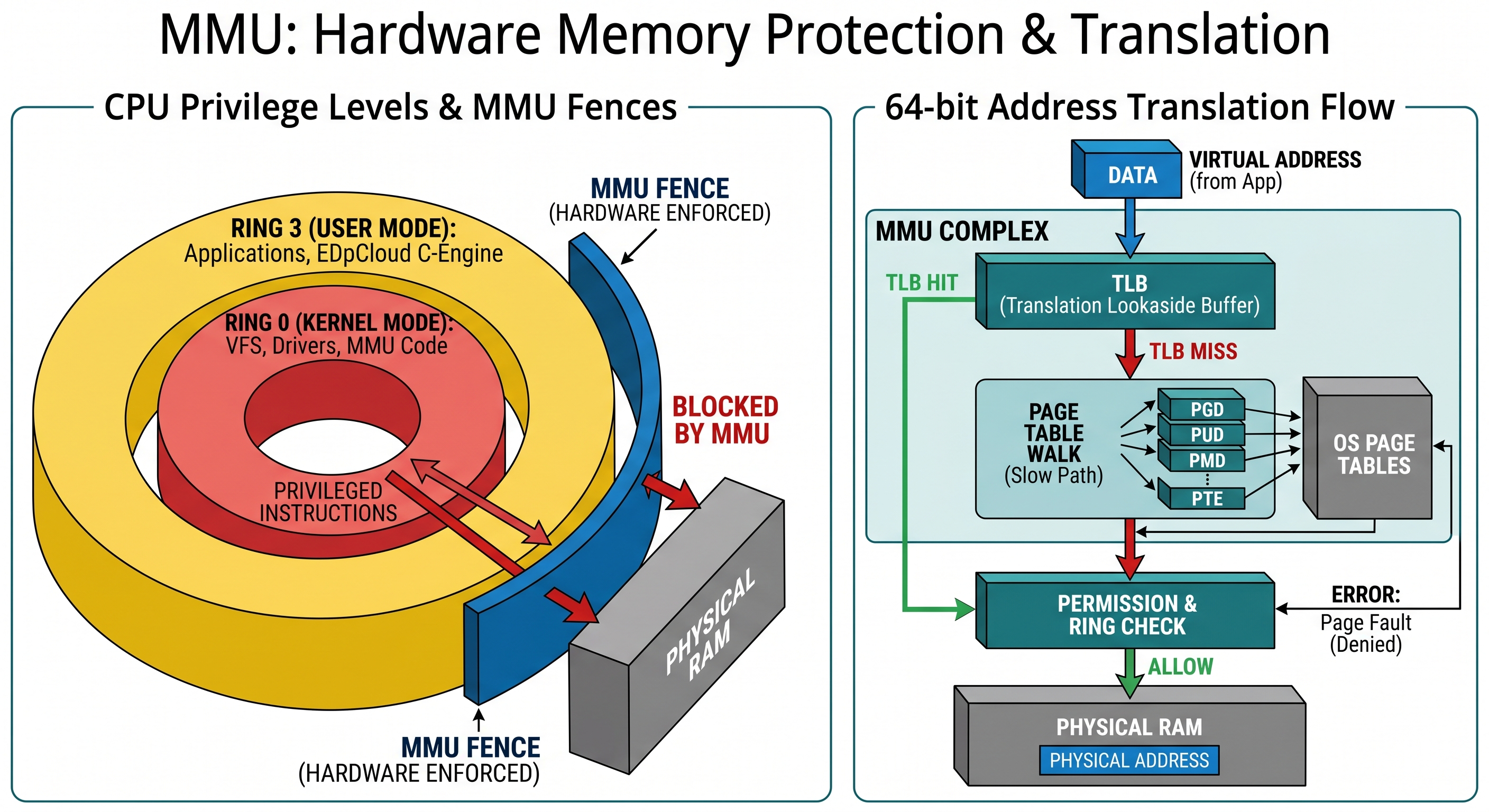
Figure 2: Hardware-level memory protection and the Virtual-to-Physical translation flow.
2.1 CPU Rings and the TLB Flush “Tax.”
The MMU enforces Privilege Rings (Ring 0 for Kernel, Ring 3 for User). In a microkernel, device drivers run in Ring 3. This means a simple disk write requires multiple context switches:
App (Ring 3) -> VFS (Ring 0) -> Driver (Ring 3) -> Hardware (Ring 0)
Each switch requires a TLB (Translation Lookaside Buffer) Flush. Flushing the TLB is mathematically expensive; the CPU must re-walk the Page Tables in slower RAM to find memory locations. Monolithic kernels (Linux/OpenBSD) avoid this “TLB tax” by keeping drivers and the VFS in the same Ring 0 memory space, allowing for Zero-Copy data transfers.
III. Advanced Data Path: Interrupts and I/O Scheduling
The final piece of the architectural puzzle is how the kernel handles asynchronous hardware. When an NVMe drive completes a write or a packet arrives at a NIC, an interrupt is triggered.
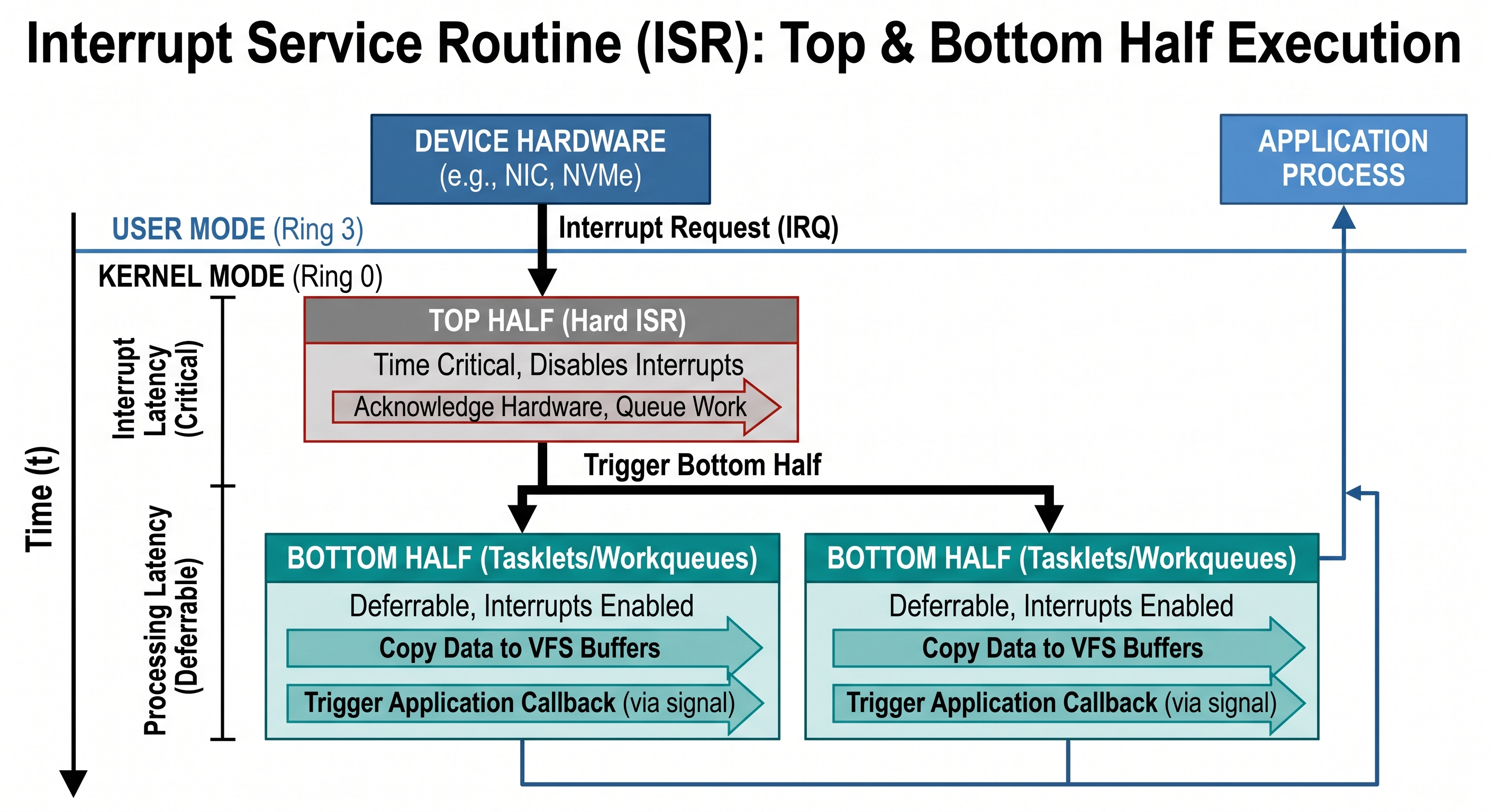
Figure 3: Breaking down the asynchronous path: ISR Top Half vs. Bottom Half processing.
3.1 Interrupt Handlers: Top Halves vs. Bottom Halves
Modern kernels split interrupt processing to maintain responsiveness:
- The Top Half: Executes immediately and disables further interrupts to acknowledge the hardware.
- The Bottom Half (Tasklets/Workqueues): Performs the heavy lifting, such as copying data into VFS buffers. In a monolithic architecture, these run in kernel context with minimal overhead, whereas microkernels require IPC to a user-space driver, adding latency.
3.2 I/O Schedulers: Merging and Deadlines
The kernel doesn’t just send data to the disk as it arrives; it uses an I/O Scheduler to merge adjacent requests and reorder them based on Deadline Scheduling. This ensures replication traffic doesn’t starve the primary application’s performance.
IV. Conclusion: The Strategic Intersection
Performance is an architectural byproduct. By leveraging the modular monolithic design of Linux and the security-hardened MMU policies, we can build replication engines like EDpCloud that satisfy the throughput requirements of modern NVMe storage while maintaining the rigorous isolation required for the 2026 security environment.
Read also:
- Looking for a high-performance Attunity alternative for your Unix or Linux environment? See our Definitive Technical Guide to Attunity Replacement.
- How to Replace Attunity and Repliweb: Guidelines for Repliweb and Attunity Replacement.
- For Data Protection: Learn how to implement Online Backup and Ransomware Tolerance using EDpCloud.
Share this Post